Software rasterizing hair
In the last few years, we have seen more rendering systems that lean on software rasterization. It’s an optimal choice for small triangles (~1 px wide) or thin triangles that span many pixels (especially diagonals). Two of the most known examples are UE5’s Nanite (which I’ve reimplemented in Nanite WebGPU) and Frostbite’s hair system (which I’ve reimplemented in Frostbitten hair WebGPU). Basic software rasterization for triangles has been described countless times e.g.:
- “The barycentric conspiracy” and “Optimizing the basic rasterizer” by Fabian “ryg” Giesen.
- “Rasterization” by Scratchapixel.
- “Rasterising a triangle” by Jason Tsorlinis.
In this article, we will see the rasterization algorithm for hair. Starting from a file that contains strand points in 3D space and ending on pixel attributes inside a quad. First, we will see the required 3D transformations to produce projected vertices. Then we will go over triangle rasterization basics, and see the same function applied to quads. We will also need coordinates inside each rasterized hair segment to compute attributes. For each section, I will also link the code from my “Frostbitten hair WebGPU” so you can see how this works in practice.
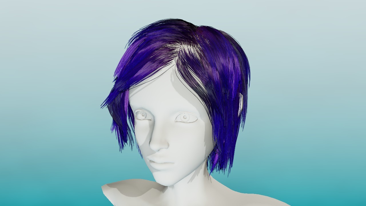
Software-rasterized hair with analytical anti-aliasing and order-independent transparency. Screen from my Frostbitten hair WebGPU.
Basic terminology
Let’s go over some terminology:
- Hair strand. Each single hair strand is created from connected points. It anchors to the head at the root point and ends at the tip point.
- Points. Each strand contains the same number of points. The first point is the root, last is the tip.
- Segment. Fragment of the strand between 2 consecutive points. If the strand has N points, it has N-1 segments.
- Tangent. A normalized vector from to . The last point for each strand (tip) has the same tangent as its predecessor. Tangents are always precalculated in a separate GPU buffer.
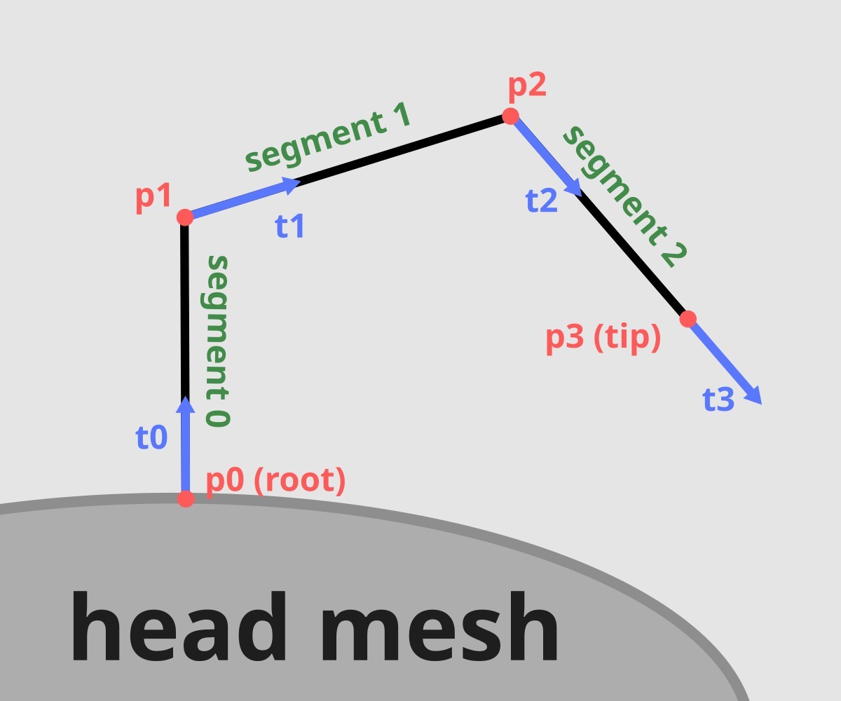
Single hair strand. The root is the first point in the strand, and the tip is the last. If there are 4 points, there are 3 hair segments. Each point has a tangent vector.
Projecting spline points
In Blender, the hair particle system is a collection of splines. Splines have control points. Everyone has seen the smoothness of bezier curves, etc. Real-time representations usually quantize each strand into discrete points - I do it in my Blender exporter. The number of points per strand is customizable and depends on the hairstyle. Short hair can get away with as little as 3 points. For example, my Frostbitten hair WebGPU uses 16 points per strand. Increasing the number of points provides a smoother look at the cost of complexity. The rendering performance hit depends on the selected technique. As I’ve discovered, in Frostbite’s tech, the cost evaluation is quite complicated. While you have to process more segments in the tile pass, the fine pass often reaches enough pixel/tile “opaqueness” to return early during the processing. This optimization happens regardless of strand count.
The question now stands: “How to turn connected points into pixel coordinates?“. We will be using billboards that have width controlled by fiberRadius parameter. Increasing fiberRadius makes each strand wider.
Projecting hair as billboards
Billboard always faces the player. It’s a plane whose normal points toward the camera. We can calculate the vertex coordinates inside the shader. For each hair point, we have a tangent vector that points toward the next point. From the definition of the cross product, we can find a vector perpendicular to both the tangent and the toward-camera vector. The coordinates for 2 vertices are given by moving along this vector. The first point is moved by fiberRadius, the other by -fiberRadius. Lastly, we multiply by the view-projection matrix.
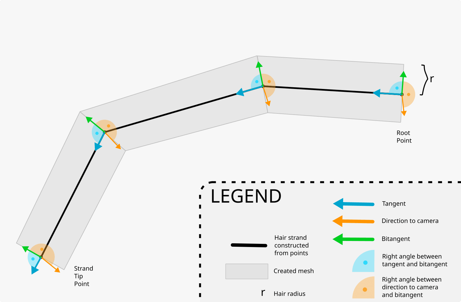
Algorithm for hair billboard renderer. Tangent - vector toward the next point (unless it’s a tip/last point). Bitangent - a vector at a right angle to both tangent and to-camera vector. Each mesh’s vertex is created by moving fiberRadius along the bitangent (with either positive or negative magnitude). An alternative way to visualize this is to imagine a plane created from tangent and to-camera vectors. Bitangent is the normal vector of this plane.
struct ProjectedStrandPoint {v0: vec2f, // in pixelsv1: vec2f, // in pixelsdepth0: f32,depth1: f32,}let segmentStartPoint = projectHairPoint(strandIdx, pointIdx);let segmentEndPoint = projectHairPoint(strandIdx, pointIdx + 1);fn projectHairPoint(strandIdx: u32, pointIdx: u32) -> ProjectedStrandPoint {// positionlet p_OBJ = _getHairPointPosition(_pointsPerStrand, strandIdx, pointIdx).xyz;let p_WS: vec4f = _modelMat * vec4f(p_OBJ, 1.0);// tangentlet t_OBJ = _getHairTangent(_pointsPerStrand, strandIdx, pointIdx).xyzlet t_WS: vec4f = _modelMat * vec4f(t_OBJ, 1.0);// Calculate bitangent vector// (cross between tangent and to-camera vectors)let towardsCamera: vec3f = normalize(_cameraPositionWS.xyz - p_WS.xyz);let right: vec3f = normalize(cross(t_WS.xyz, towardsCamera)).xyz * _fiberRadius;let v0_WS = vec4f(p_WS.xyz - right, 1.0);let v1_WS = vec4f(p_WS.xyz + right, 1.0);let v0_NDC: vec3f = projectVertex(_viewProjMat, v0_WS);let v1_NDC: vec3f = projectVertex(_viewProjMat, v1_WS);return ProjectedStrandPoint(ndc2viewportPx(_viewportSize.xy, v0_NDC),ndc2viewportPx(_viewportSize.xy, v1_NDC),v0_NDC.z,v1_NDC.z);}fn projectVertex(mvpMat: mat4x4f, pos: vec4f) -> vec3f {let posClip = mvpMat * pos;let posNDC = posClip / posClip.w;return posNDC.xyz;}fn ndc2viewportPx(viewportSize: vec2f, pos: vec3f) -> vec2f {let pos_0_1 = pos.xy * 0.5 + 0.5; // to [0-1]return pos_0_1 * viewportSize.xy;}
Link to “Frostbitten hair WebGPU”: swRasterizeHair.wgsl.ts # projectHairSegment().
You might be considering calculating the right vector in view space with let towardsCamera = vec3f(0, 0, 1). It will not work. Half of the strands will render with towardsCamera.z = 1, the rest with towardsCamera = -1. I’m not sure why (view space is weird), so I switched to world space calculations.
For each segment (consisting of start and end points) we now have 4 projected points. Use them as vertices in quad rasterization.
Software rasterization
First, we will find a way to check on which side of a line the point lies. With 3 lines this function allows to rasterize a triangle. With 4 lines we get quad.
Edge function
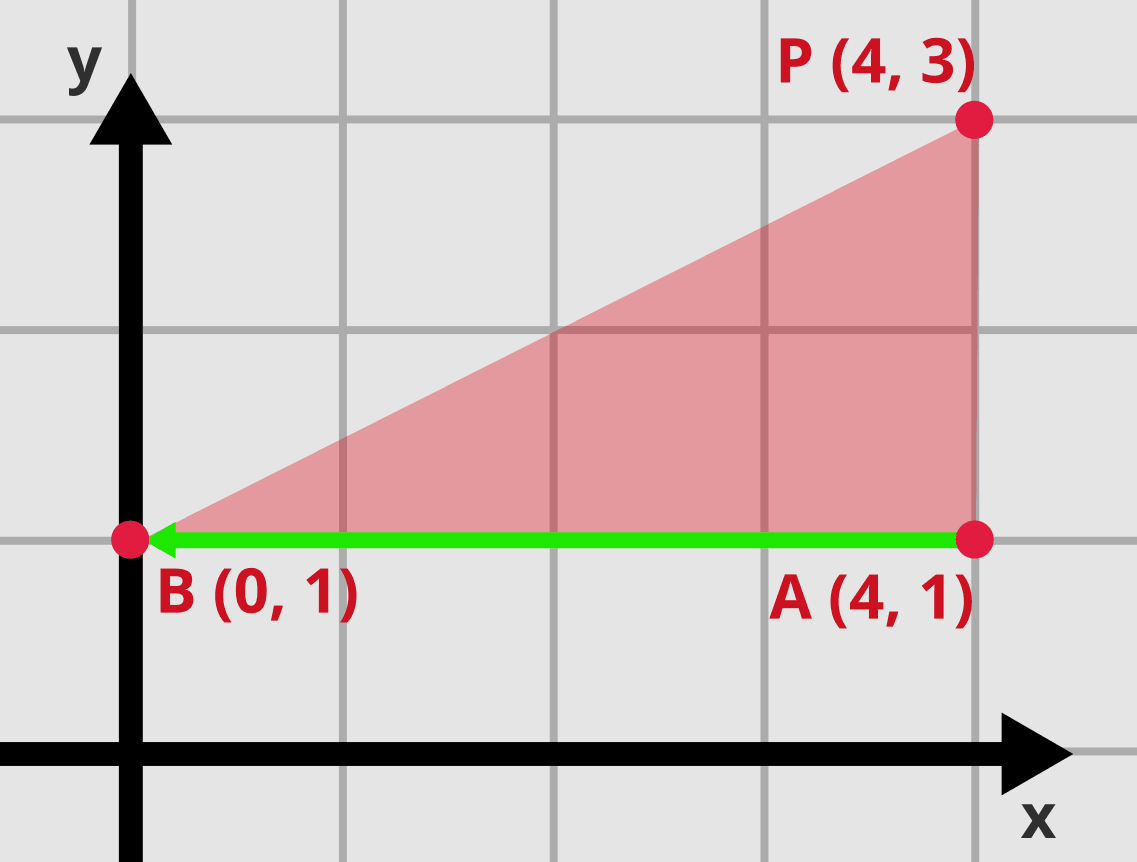
We start with a line and a point . Our goal is to check on which side of the line the point lies. Let’s mark 2 points on this line: , and calculate the area of triangle using the Shoelace formula:
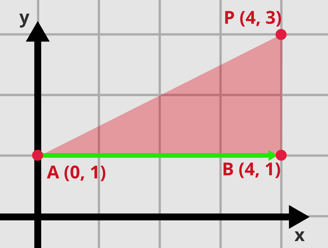
Triangle with points: A=(0, 1), B=(4, 1), P=(4, 3). Notice the direction of vector AB and the relative position of point P.
Plugging the values:
Let’s try swapping coordinates for points and :
The same triangle after we swapped points A and B. Notice the direction of vector AB and the relative position of point P.
Wait, how can an area of a triangle be negative? Well, you should take the absolute value here. But that was not our goal. We are only interested in why the sign switched.
Let’s now consider the relative positions of the 3 points. In the first example, imagine you are standing on point and looking toward point (along the green arrow). Then, the point is on your left side. Repeat this after swapping positions of points , and (again, look at the green arrow). The point is now on the right side. Generalizing this observation, the edge function results in one of 3 outcomes:
- If the value is negative, the point lies on one side of the line.
- If the value is positive, the point lies on the other side of the line.
- If the value is 0, the point lies on the line.
You might also notice that the result depends on the clockwise/counterclockwise order of vertices. This is useful for triangle culling. We will not use this property for hair.
Using the edge function to rasterize triangles
Now we can check which “side” of the line a point (or a pixel) lies. If we have 3 lines, there will be an area that lies on the same side of each line.
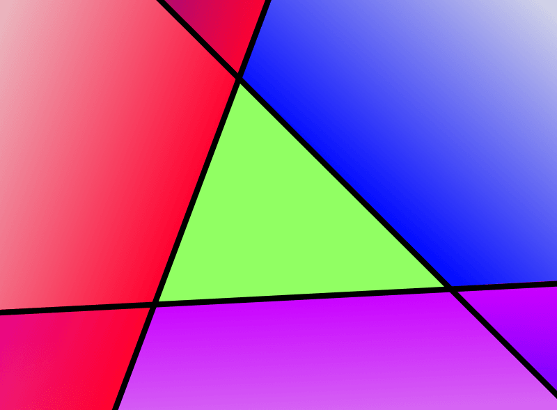
The area within 3 lines is a triangle.
This is how the simplest triangle rasterization works. For each pixel in the canvas, calculate the value for all 3 edge functions and check if all are negative (or positive depending on vertex winding). You can optimize this by calculating triangle bounds. For triangle with vertices v0, v1, v2 write following rasterization code:
var boundRectMin = floor(min(min(v0, v1), v2));var boundRectMax = ceil (max(max(v0, v1), v2));// scissorboundRectMin = max(boundRectMin, vec2(0));boundRectMax = min(boundRectMax, _viewportSize.xy);for (var y = boundRectMin.y; y < boundRectMax.y; y += 1) {for (var x = boundRectMin.x; x < boundRectMax.x; x += 1) {let p = vec2f(x, y); // floats. See below for sampling offsetlet C0 = edgeFunction(v2, v1, p); // v2, v1 order depends on CW/CCWlet C1 = edgeFunction(v0, v2, p);let C2 = edgeFunction(v1, v0, p);if (C0 >= 0 && C1 >= 0 && C2 >= 0) {// pixel inside triangle v0, v1, v2putPixel(p, COLOR_BLUE);}}}fn edgeFunction(v0: vec2f, v1: vec2f, p: vec2f) -> f32 {return (p.x - v0.x) * (v1.y - v0.y) - (p.y - v0.y) * (v1.x - v0.x);}
Often you would also use the result of edgeFunction() to compute barycentric coordinates. This article focuses on hair (rendered as quads), and we will not use this property.
Half of the pixel offset
Another issue is sampling. If you take a single sample per pixel, you should offset by vec2f(0.5, 0.5) to sample in the center of the pixel. With multisampling, you should apply an appropriate offset to each sample. Read the specification for your graphic API to get exact values. Some APIs allow you to provide custom sampling patterns e.g. VK_EXT_sample_locations(). This is important if you are mixing hardware and software rasterization, e.g. by using a depth buffer.
While at it, you should also check the exact triangle rasterization rules (e.g. top-left rule, etc.).
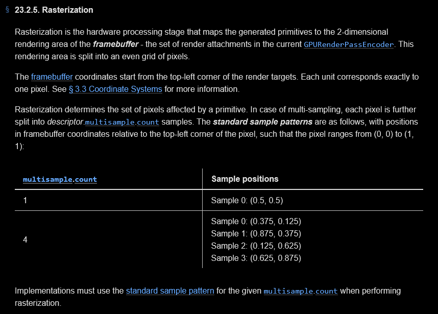
Excerpt from rasterization rules for WebGPU.
Using the edge function to rasterize quads
Rasterizing quads is much more complicated. You have to call edgeFunction() 4 times.
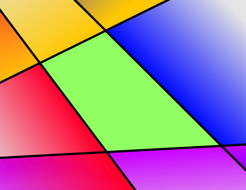
The area within 4 lines is a quad.
var boundRectMin = floor(min(min(v00, v01), min(v10, v11)));var boundRectMax = ceil (max(max(v00, v01), max(v10, v11)));// scissorboundRectMin = max(boundRectMin, vec2(0));boundRectMax = min(boundRectMax, viewportSize.xy);for (var y = boundRectMin.y; y < boundRectMax.y; y += 1) {for (var x = boundRectMin.x; x < boundRectMax.x; x += 1) {let p = vec2f(x, y); // floatslet C0 = edgeFunction(v01, v00, p);let C1 = edgeFunction(v11, v01, p);let C2 = edgeFunction(v10, v11, p);let C3 = edgeFunction(v00, v10, p);if (C0 >= 0 && C1 >= 0 && C2 >= 0 && C3 >= 0) {// pixel inside quad v00, v01, v10, v11putPixel(p, COLOR_LIGHT_PURPLE);}}}
The notation for
v0-andv1-is relative to the hair segment.v0-denotes vertices near the start point.v1-denotes vertices near the end point.
Given what’s written till this point, you should be able to software rasterize hair based on imported strand points.
Link to “Frostbitten hair WebGPU”: hairTilesPass.wgsl.ts.
Optimization (or not)
Let’s look at the edge function again:
We are then iterating over . A common optimization is to write the edge function in a form that matches . This way, when we iterate over successive pixels in a row (only changes) we can just add . The part does not change. No reason to re-evaluate the whole edge function. Similar when switching to the next row. The code below might be helpful at this point.
In a triangle, there are 3 edges. So we precompute 3 different values of A, B, and C (total 9 floats). Given 2 vertices that create an edge, we have the following formulas:
Invert the signs for clockwise/counterclockwise conversion.
For triangles, this is around 7% faster. Measured in one of the test scenes in Nanite WebGPU.
Since quad has 4 edges, we precompute 4 sets of A, B, C. Unfortunately, this is quite a lot of registers. In “Frostbitten hair WebGPU”, HairFinePass uses this optimization, while HairTilesPass does not.
(EDIT 28.09) I’ve rewritten HairFinePass to parallelize over pixels in a tile. Now it also uses edge function.
Quad rasterization if you use this optimization:
let CC0 = edgeC(v01, v00);let CC1 = edgeC(v11, v01);let CC2 = edgeC(v10, v11);let CC3 = edgeC(v00, v10);var CY0 = boundRectMin.x * CC0.A + boundRectMin.y * CC0.B + CC0.C;var CY1 = boundRectMin.x * CC1.A + boundRectMin.y * CC1.B + CC1.C;var CY2 = boundRectMin.x * CC2.A + boundRectMin.y * CC2.B + CC2.C;var CY3 = boundRectMin.x * CC3.A + boundRectMin.y * CC3.B + CC3.C;for (var y: f32 = boundRectMin.y; y < boundRectMax.y; y += 1.0) {var CX0 = CY0;var CX1 = CY1;var CX2 = CY2;var CX3 = CY3;for (var x: f32 = boundRectMin.x; x < boundRectMax.x; x += 1.0) {if (CX0 >= 0 || CX1 >= 0 || CX2 >= 0 || CX3 >= 0) {// pixel inside quad v00, v01, v10, v11putPixel(p, COLOR_IRIS);}CX0 += CC0.A;CX1 += CC1.A;CX2 += CC2.A;CX3 += CC3.A;}CY0 += CC0.B;CY1 += CC1.B;CY2 += CC2.B;CY3 += CC3.B;}struct EdgeC{ A: f32, B: f32, C: f32 }fn edgeC(v0: vec2f, v1: vec2f) -> EdgeC{// from edgeFunction() formula we extract: A * p.x + B * p.y + C.// This way, when we iterate over x-axis, we can just add A for// next pixel, as the "B * p.y + C" part does not change.// Uses WebGPU vertex winding (signs inverted wrt. math above)var result: EdgeC;result.A = v1.y - v0.y; // for p.xresult.B = -v1.x + v0.x; // for p.yresult.C = -v0.x * v1.y + v0.y * v1.x; // restreturn result;}
Link to “Frostbitten hair WebGPU”: processHairSegment.wgsl.ts (part of HairFinePass). My project has 2 different passes that use software rasterization.
HairTilesPassis faster without this optimization.
Segment-space coordinates
This leaves us with the last question: “How to calculate barycentric coordinates for pixels inside the quad?“. Well, we don’t. For hair, we need coordinates in “segment space”, according to 2 axes. I’m not sure if there is some industry-standard algorithm for this, so I’ve used my own. I will highlight where it has some issues, but you can always check the demo page for Frostbitten hair WebGPU to see how big of a problem it is in practice. A lot of value is in realizing what problem we are trying to solve. You can find the complete code at the end.
There are algorithms to calculate barycentric coordinates in a quad. I spend 2 hours trying to get them to work. This was one of the first days of writing “Frostbitten hair WebGPU”. Since I still had the whole app to write, I decided to use something good enough. I did not change it later and it is present in the final version.
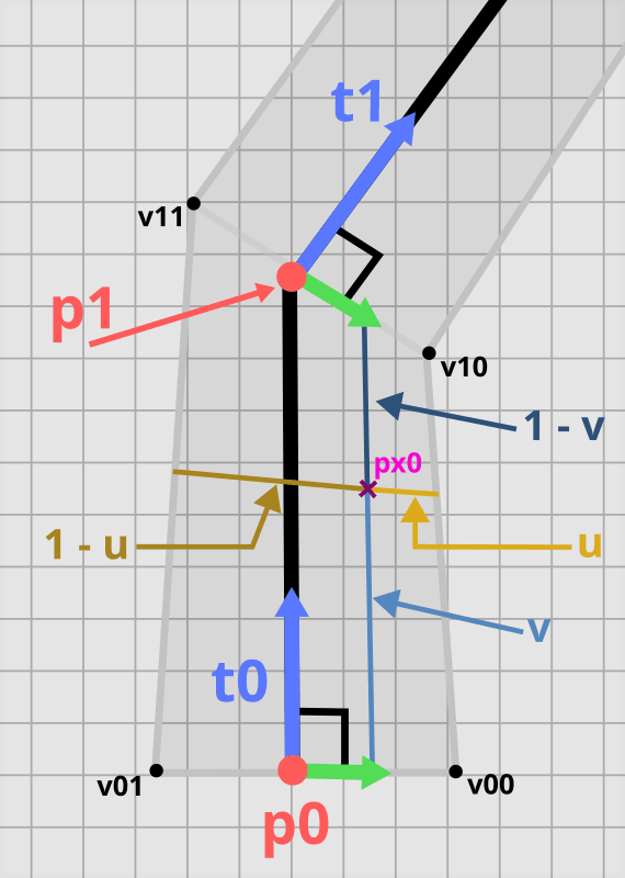
Hair segment on a pixel grid. Calculating segment space coordinates for pixel px0. v is the coordinate along the long axis, and u is the coordinate along the short axis. The picture also contains marked 1 - v and 1 - u. Tangents marked in blue, bitangents in green. Points v00, v01, v10, v11 are the vertices we calculated in the previous section.
Calculation for long axis
- Calculate a line that goes through the start and end points of the segment.
- Project the pixel onto the line.
- Calculate the distance from the segment start point to the projected pixel.
- Divide this distance by segment length. Saturate the result so that it is between 0 and 1.
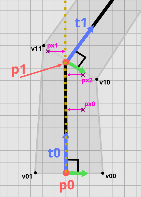
Calculating long axis coordinates for pixels px0, px1, and px2 by projecting onto p0-p1 line (marked in yellow).
Looking at the image, there are obvious flaws. Pixel is projected beyond the end segment. It requires the call to saturate(). The value for is also incorrect. The perceived error depends on the hair width and angle between subsequent tangents. It’s not noticeable as the hair is thin and most rendering techniques provide anti-aliasing with transparency.
If you look at the image and think there is an obvious better algorithm, then I guess I’ve made damn good illustrations.
Calculation for short axis
Given the value for the long axis, it’s easier to get the second coordinate. Notice that the segment’s end width depends on the tangent of the next segment. Only the last segment (near the strand’s tip) has the same width near both points.
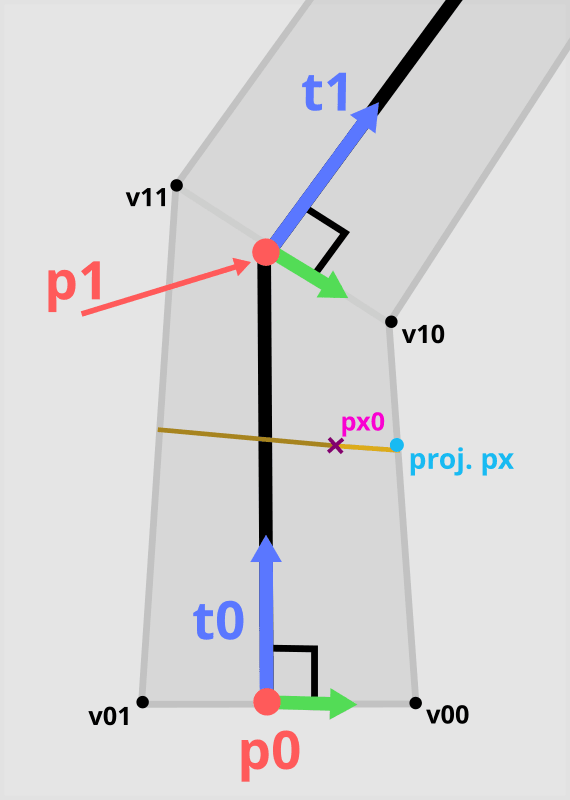
Calculating short axis coordinates for pixel px0 by projecting it onto the side edge.
- Calculate the
width near the segment's start. - Calculate the projected
width near the segment's endusing scalar projection (dot product). - Strand
width near the pixelis a linear interpolation of start and end width using the coordinate for the long axis. - Project the pixel onto one of the side edges of the segment.
- Calculate the distance from the pixel to the projected pixel.
- Divide this distance by the segment’s
width near the pixel. Saturate the result so that it is between 0 and 1.
Alternatively, you could find points on both side edges: e0 = mix(v00, v10, v), e1 = mix(v01, v11, v). Then u = distance(pixel - e0) / distance(e0 - e1).
Link to “Frostbitten hair WebGPU”: swRasterizeHair.wgsl.ts.
Once you have this value, use it to e.g. estimate alpha coverage:
fn getAlphaCoverage(interpolationWidth: f32) -> f32 {// $interpolationWidth is in range 0..1.// Transform it so strand middle is 1.0 and then 0.0 at edges.var alpha = 1.0 - abs(interpolationWidth * 2. - 1.);// you can change linear interpolation to quadraticif (HAIR_USE_ALPHA_QUADRATIC) {alpha = sqrt(alpha);}// or modify alpha with a magic value if you want to make the hair thickeralpha = saturate(alpha * HAIR_ALPHA_MULTIPLIER);return alpha;}
Code
struct ProjectedSegment {v00: vec2f,v01: vec2f,v10: vec2f,v11: vec2f,}/*** result[0] - value in 0-1 range along the width of the segment.* 0.0 means on the one side edge, 1.0 is on the other one* result[1] - value in 0-1 range along the length of the segment,* 0.0 is near the segment start point,* 1.0 is near the segment end point*/fn interpolateHairQuad(projSeg: ProjectedSegment, pxPos: vec2f) -> vec2f {// strand point for edge at the start of the segmentlet startEdgeMidpoint = (projSeg.v00 + projSeg.v01) / 2.0;// strand point for edge at the end of the segmentlet endEdgeMidpoint = (projSeg.v10 + projSeg.v11) / 2.0;// project the pixel onto the line that crosses both segment pointslet cProjected = projectPointToLine(startEdgeMidpoint, endEdgeMidpoint, pxPos);// normalized distance from the start of the strand's segment. Range: [0..1]let d1 = length(cProjected - startEdgeMidpoint) /length(endEdgeMidpoint - startEdgeMidpoint);// start edge is perpendicular to tangent of the current segmentlet widthStart = length(projSeg.v00 - projSeg.v01);// 'End' edge is at the angle to segment's tangent.// Its direction is determined by the NEXT segment's tangent.// Project the 'end' edge onto the 'start' edge// using the geometric definition of dot product.let widthEnd = widthStart * dot(normalize(projSeg.v00 - projSeg.v01),normalize(projSeg.v10 - projSeg.v11));let expectedWidth = mix(widthStart, widthEnd, d1);// project pixel onto one of the side edgeslet e1 = projectPointToLine(projSeg.v00, projSeg.v10, pxPos);// distance between pixel and its projection on the edge.// Divided by full width of the strand around that pointlet d0 = saturate(length(pxPos - e1) / expectedWidth);return vec2f(d0, staturate(d1));}/** https://stackoverflow.com/a/64330724 */fn projectPointToLine(l1: vec2f, l2: vec2f, p: vec2f) -> vec2f {let ab = l2 - l1;let ac = p - l1;let ad = ab * dot(ab, ac) / dot(ab, ab);let d = l1 + ad;return d;}
Per-pixel linked lists and tiles
To render nice, soft-looking hair you need to handle antialiasing and transparency. With thousands of hair strands, alpha blending is a challenge. There are many ways to achieve order-independent transparency (OIT), but per-pixel linked lists (PPLLs) are the most common. The technique does the following (for each pixel):
- Collect hair samples into a list.
- Sort hair samples by depth.
- Blend the samples.
Notice there are 2 phases to this algorithm. First, process each hair segment and write per-pixel data. In the second step, process the list for each pixel. These steps naturally map to 2 separate GPU commands.
Yet, there is a flaw in this algorithm. How much memory to allocate? Often a magic avgHairSamplesPerPixel is introduced. Total allocation is then screenSizeInPixels * avgHairSamplesPerPixel * sizeof(HairSample). Then someone will come with a Retina display.
“High-Performance Software Rasterization on GPUs” by Samuli Laine and Tero Karras has a different setup. We will use the idea of coarse and fine rasterizer to split the screen into tiles.
The first step (coarse rasterizer) outputs a list of hair segments per tile. The memory needed is tileCount * avgHairSegmentsPerTile * sizeof(HairSegmentId).
In fine rasterizer, each workgroup grabs a tile from a global list. The number of workgroups is fixed and independent of tile count. Use the GPU task queue to distribute the workload. One thread represents a single pixel. The first thread fetches hair segment data, projects it, and broadcasts the partial result. Then, each thread compares its pixel using the edge function. The results are stored in a temporary buffer of size numberOfWorkgroups * tileSize * tileSize * avgHairSamplesPerPixel * sizeof(HairSample). Still inside the fine rasterizer, we sort and shade the pixels.
I’ve glossed over how PPLLs are actually implemented using 2 separate buffers. One is for list heads, and one is for the actual data. I hope I gave you a good approximation of how Frostbitten hair WebGPU works.
Summary
In this article, we have seen how to turn hair splines into real-time rendered pixels. The techniques are not complicated, but their application is rarely discussed. Given the recent spotlight on software rasterization, many companies will move in this direction. Due to inherent complexity, hair rendering is always implemented as a separate subsystem. The knowledge from this article should be enough to start implementing techniques from Robin Taillandier and Jon Valdes’s “Every Strand Counts: Physics and Rendering Behind Frostbite’s Hair”. After watching the presentation you can move straight into the codebase of my Frostbitten hair WebGPU.